Aberlink 3D software is not only ‘easy-to-use’, but also has the depth of functionality to make it the choice for either first time users or full-time inspection professionals. Aberlink CMM software updates will be available free of cost till machine life. Software suitable for coordinate measuring machines with either touch, scanning or vision systems.
The whole philosophy for Aberlink is to make measurement easy. Aberlink 3D software has been written by engineers for engineers and sets the industry standard for simple-to-use software. Designed around a graphical interface, Aberlink 3D can work in 2D or 3D, on manual or CNC CMMs and is equally at home when used with either touch, scanning or vision systems.
Aberlink 3D software is not only ahead of its competition in being the industry standard for ‘easy-to-use’ software, but also has the depth of functionality to make it the choice for either occasional users or full-time inspection professionals.
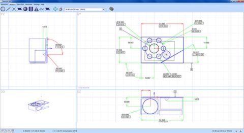
Aberlink 3D software is revolutionary. For example, Feature Predict enables you to just take measurement points and the software automatically determines if you are measuring a Plane, Line or Circle feature. Move from feature to feature and the software predicts what you are measuring. As a component is measured a representation of it is built up on the screen. The user simply clicks on the measured features to call up dimensions exactly as they would appear on a drawing.
Inspection reports can be in the form of fully dimensioned graphical representations as created on the screen, or tabulated reports in various formats that can show nominals, tolerances, errors, pass/fails, geometric tolerances etc. These reports can also be output to an Excel spreadsheet.
Further reports are available to show the form of features (roundness, straightness etc.), hole or point positions, or complete batch results on one report. The user’s company name also appears on all outputs.
Every time a component is inspected, a programme for measuring subsequent components is automatically created. The software also calculates ‘safe’ moves between features, even when the probe is indexing – just another thing that the operator doesn’t have to worry about.
Feature Inspection |
Programme Tools |
| •Automatic measurement routines
•Powerful interactive graphics window •Automatic feature recognition •2D and 3D inspection •Geometric feature inspection •Free form curve inspection •DXF data import/export •STEP and IGES export •Feature construction •Intelligent feature projection •GD&T dimensions and tolerances •Digital Read Out (DRO) |
•Teach & repeat programming
•Drag and drop programme editor •Run programs from any point •Measure a subset of features •Simple object-based programming •No complex programming language •Automated batch inspection •Password protect programmes •Automatic safety moves •Feature replicator |
Report Formats |
|
| •Engineering drawing GD&T report
•Simple PASS/FAIL report •Form plots •Batch summary report •Tabulated reports •Graphical fly-out labels •Drag & drop reporting •Real-time SPC •Combine multiple views •Export to Excel •Historical data reporting |
|
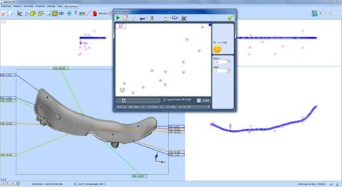
The Aberlink CAD Comparison software module enhances Aberlink 3D with the capability to compare measured points to a CAD model. This may be the best way to measure complex geometries, or to inspect parts for which drawings do not exist.
Powerful alignment routines allow measurement points to be best-fitted to the model. Colour coded errors can then be displayed on the model to produce both graphical and tabulated reports that are extremely clear and very easy to understand.
Aberlink’s CAD comparison module allows the input of either STEP or IGES files as standard and allows reports to be exported as an Excel spreadsheet. It really does make measuring complex parts easy, whether on a manual or CNC CMM.
CAD Formats |
Alignments |
| •IGES and STEP import and export
•DXF export •Re-scale Models •Simple measurement of complex parts |
•Point cloud best-fit
•Feature best-fit •Best-fit constraints |
Report Formats |
|
| •On CAD fly-out labels
•Colour deviation whiskers •Colour point markers •Configurable colour options •Combine multiple views •Graphical and tabulated reports •Export to Excel |
|
For many years Aberlink 3D software has been setting the industry standard for both ease of use and speed of programming. However, until now this has been best done by using the teach-andrepeat method of programming when measuring a component. But what if you want to prepare the measurement programme before you even have the first component? Now, we are pleased to introduce our new CAD programming module, which in true Aberlink fashion, allows the simplest programming possible from either an IGES or STEP CAD model.
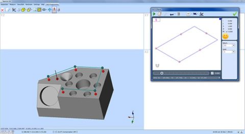
If you can use Aberlink 3D software then you will already know how to use the CAD programming module – it couldn’t be easier. Rather than taking measurement points on a component, you can now just click on the surface of the model where you would like the points to be taken.
Feature Predict works in the same way as when measuring, for instance, if you click in four places on the same plane on the model, then the software will automatically create a Plane Measure unit with those four points in it. Then click on a different feature and it will automatically close the Plane window and look for another feature. If you click on a circular feature it will take just one click to produce a circle or two for a cylinder. Suddenly programming in Aberlink 3D just got even easier!
Aberlink’s CAD programming module can be used either on the CMM or off-line… nothing could be more straightforward.


