


Excessive web deflection is dangerous for the engine. The cause may be faulty or damaged crankshaft, damaged bearing, poor bearing alignment, excessive bearing clearance or slackness, faulty flanging to transmission, flywheel or Vee Belt pulley, etc.
FEATURES:
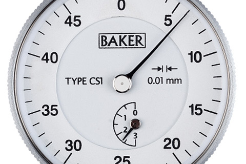
- Every gauge carries a calibration certificate giving actual values
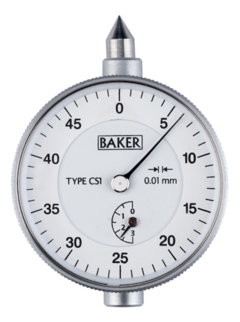
- Crankshaft Gauge measures the Web deflection of a crankshaft
- The BAKER Crankshaft Gauge is developed to identify and avoid the problems mentioned above
- The Gauge covers web-to-web distance of 60-600 mm
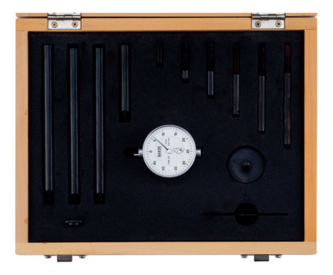
- Supplied in a sleek wooden box
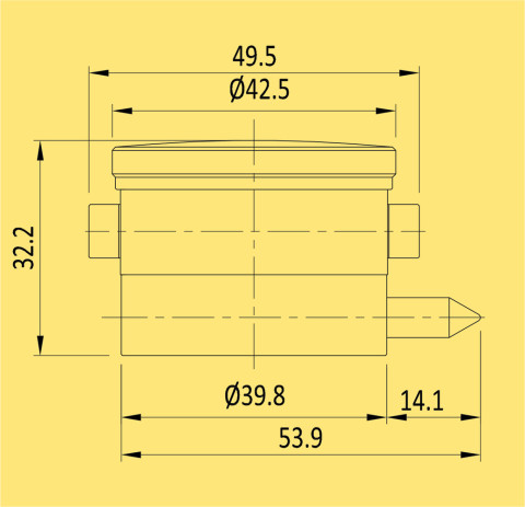
- Gauge contacts are pointed & fit into dimples in the webs. A heavy spring pressure ensures that the Gauge is restrained but is free to turn in relation to the crankshaft. An adjustable balance weight restrains the Gauge against rotation of the crankshaft, so that the dial always faces the inspector
| Type | Reading | Range | Graduation | ||||
|---|---|---|---|---|---|---|---|
| CS1 | 0.01mm | 60-600 mm | 0-50 | ||||
| CS2 | 0.0005" | 2.4-23.6" | 0-20 | ||||
| CS3 | 0.01mm | 60-600 mm | 0-25-0 | ||||
| CS4 | 0.0005" | 2.4-23.6" | 0-10-0 |
 |
HOW TO USE BAKER CRANKSHAFT GAUGE?
|